
 |
Search | FAQ | US Titles | UK Titles | Memories | VaporWare | Digest | |||||||
| GuestBook | Classified | Chat | Products | Featured | Technical | Museum | ||||||||
| Downloads | Production | Fanfares | Music | Misc | Related | Contact | ||||||||
| Modifying RCA TV Remotes to Control CED Players | ||||||||||||||
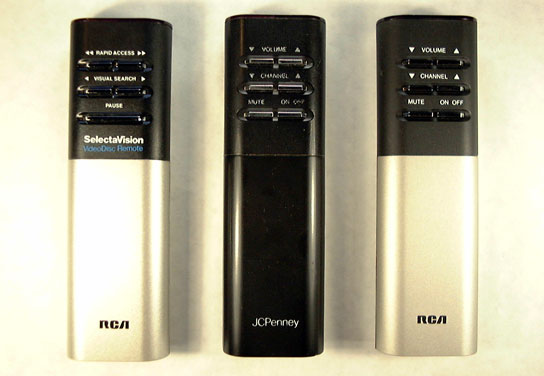
These instructions are for modifying RCA's CRK33 series of television infrared remote controls manufactured during the CED era so the units can control the SGT250, SJT300, SKT300, and 686-5705 CED players. The above picture shows an original VideoDisc remote on the left and the corresponding CRK33 remote for an RCA television on the right. In the center is a remote for a JCPenney TV, which internally is identical to the RCA TV remote as RCA was OEMing JCPenney televisions back in the CED days. The only difference between the VideoDisc and TV remotes is the value of one capacitor inside the unit, which determines what general frequency range the remote is tuned to. RCA made the remotes different in this regard so owners of both a VideoDisc player and an RCA TV wouldn't experience interference between the two remotes.
All that is needed to get these CRK33 television remotes functioning with CED players is to remove the 920 pF (picofarad) capacitor C1 inside the remote and in its place solder a 560 pF Monolithic Ceramic Capacitor. The 560 pF capacitor may be requested on the Products Page.
After the new capacitor is soldered in place, the adjustment screw on transformer T1 can be rotated to fine-tune the frequency response. The following two diagrams from RCA's service literature show the remote control circuit board layout with C1 and T1 located at the left end of each diagram.

The diagram on the left is for three-LED remotes, while the diagram on the right is for two-LED remotes. These LED's labeled as CR1, CR2, and CR3 in the diagrams transmit the infrared pulses to the Photo Diode receiver on the television or VideoDisc player. Early on, RCA used three AA batteries and three LED's and later switched to a more economical design using two AA batteries and two LED's along with some other component changes. For the purpose of this modification, it doesn't matter if you use a two-LED or three-LED remote, since in both instances a 920 pF capacitor is being replaced with a 560 pF part. For a bit of CED trivia, a 560 pF capacitor is rather small in value compared to the typical discreet capacitor (the adjacent C2 on the remote circuit board is 18 times larger in value). But within the groove on a CED, the maximum change in capacitance from the deepest valley to the highest peak is only a nearly infinitesimal 0.0001 pF.
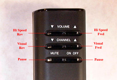
Shown here are the VideoDisc functions performed by the television remote after the capacitor substitution has been performed. The original VideoDisc remote has only one PAUSE button, while this photo indicates the MUTE and ON/OFF buttons on the TV remote perform pause. This is because there really are two separate membrane switches hidden under that wide PAUSE button on the VideoDisc remote. It may not be possible to get both of these switches to simultaneously perform pause on the TV remote, but by adjusting the screw on transformer T1, it is always possible to get the ON/OFF button to perform pause, and by rotating it further, the MUTE button may initiate the pause function as well.
Note that some VideoDisc remotes (like the one above) have the top two buttons labeled "RAPID ACCESS" while others have these buttons labeled "HI SPEED SCAN." RCA used RAPID ACCESS on the CRK34A model remote shipped with the SGT250 player to indicate a 120x blanked search where no image could be seen on the TV screen. RCA and JCPenney used HI SPEED SCAN on the CRK34C, CRK34D, CRK34E, and CRK34F remotes shipped with the other players to indicate a 120x visual search with no blanking.
These RCA and JCPenney CRK33 television remotes are more abundant than the corresponding CRK34 VideoDisc remotes, as RCA manufactured a lot of TV's using the CRK33 during the early 1980's. Over a period of several years I found more than a dozen loose TV remotes in thrift stores compared to only two loose VideoDisc remotes. In an odd twist, remote control VideoDisc players are usually found without the remote, while RCA TV remotes are usually found without the television. This is because thrift stores will typically toss the donated TV in the dumpster, but fortunately they often put the remote in a bin with other odd remote controls. The Goodwill is particularly good about doing this. These remotes also turn up in eBay auctions, although it's necessary to sift your way through a lot of auctions containing the words rca remote to find them.
Here are the step-by-step instructions for performing this modification. Besides the 560 pF capacitor (with the included piece of desoldering braid), you will need a Phillips driver, a low wattage soldering iron, and solder.
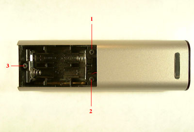 (1) Remove the battery cover and batteries from the remote, then remove the three Phillips screws that hold the two halves of the housing together.
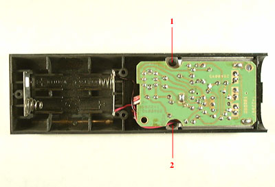 (2) Separate the lower half of the housing (it's keyed at the end opposite the battery compartment) and set it aside. Remove the two Phillips screws holding the remote control circuit board in place.
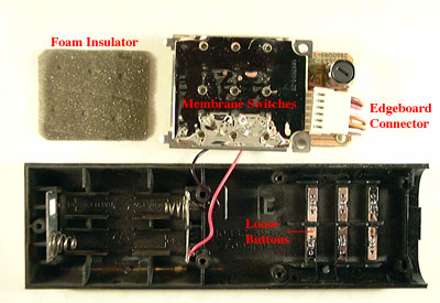 (3) With the button side of the remote facing down, pull back slightly on the circuit board to disengage the two metal clips, then rotate the circuit board out to the side of the remote housing as shown. A piece of insulating foam will be found between the membrane switches and the remote buttons. The six buttons will be loose and will simply fall out if the upper housing is inverted. Remove these and set them safely aside to prevent loss. An optional step is to remove the metal battery contacts from the housing, which can be pulled straight out with a needle nose pliers.
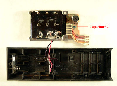 (4) Unplug the edgeboard connector to expose capacitor C1 underneath. Note that the edgeboard connector needs to later be plugged back in the same orientation to make electrical contact.
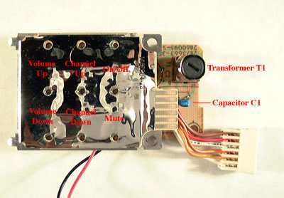 (5) This is a closer view of the circuit board with the function of the six switches labeled. These switches can be operated by simply pushing on the silver membrane above each switch. Also visible is the adjustment screw on transformer T1, which will be rotated to fine tune the circuit after the capacitor C1 has been replaced.
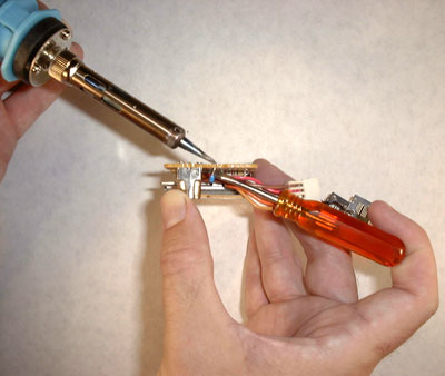 (6) This picture shows how a small blade driver can be used as a wedge to facilitate removal of the 920 pF capacitor. Lift the body of the capacitor while using the soldering iron to heat first one joint and then the other joint. In this view it can be seen that the battery contacts next to the driver handle have been removed from the housing.
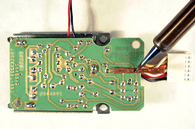 (7) Clean up the two solder pads on the circuit board using the copper desoldering braid supplied with the 560 pF capacitor. This is accomplished by placing the braid against the circuit board and heating the solder pad through it, which absorbs any remaining solder by rubbing the braid back and forth across each of the two solder pads.
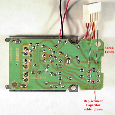 (8) From the other side of the circuit board, insert the leads of the 560 pF capacitor through the holes on the solder pads. Push the leads through so the replacement capacitor is in about the same position as the old one. This capacitor is not polarized, so the orientation of the two leads does not matter. Solder the two joints from the side of the circuit board visible in this picture, then snip off the excess leads.
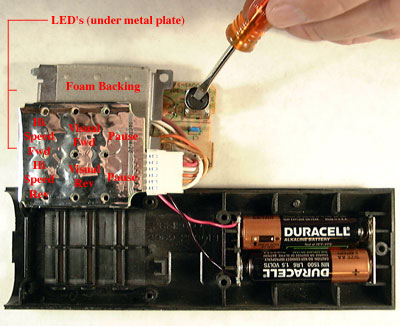 (9) Plug the edgeboard connector back in place (remember correct orientation) and the unit is ready for fine adjustment. This is accomplished by operating the remote with batteries installed as shown in this picture. Note also in this picture that handling has caused the board holding the membrane switches to become separated from its foam backing. This is of no consequence, as the board got stuck to that foam simply by years of compression and will be held back in place after reassembly. Follow the steps below to fine tune the circuit for VideoDisc player use.
(10) Install two or three AA batteries in the remote, depending on the specific model. It may first be necessary to push the metal battery contacts back into place if they were removed.
(11) Load a VideoDisc into an appropriate remote control player (models SGT250, SJT300, SKT300, or 686-5705) and let it initiate playback.
(12) Point the LED's shown in the assembly above at the player and press either of the membrane switches labeled pause to see if that function will activate on the player. This is unlikely to happen without some adjustment of the screw on transformer T1. Pause is a toggle function, so when working, pressing the button once puts the player in pause and pressing it again resumes normal playback.
(13) The screw on transformer T1 will most likely need to be rotated counterclockwise (looking down at the screw) to fine tune the circuit. Rotate the screw 1/8 to 1/4 a rotation counterclockwise and test the pause button corresponding to ON/OFF. It will probably now initiate pause on the player. If not, rotate the screw another 1/8 to 1/4 a rotation counterclockwise and try pausing the player again. When rotating the screw counterclockwise, you will find that first the ON/OFF button will initiate pause and with further rotation ON/OFF will stop doing this, but the MUTE button will usually start initiating pause. Between these two points there may be a very narrow range of adjustment where both buttons will initiate pause, but often it's easier to simply adjust the circuit so ON/OFF initiates pause. When the pause function is working, test the top four buttons to see if they are performing the search functions. It may be necessary to fine tune the frequency a little more within the range of adjustment that provides pause. Note that it may be necessary to press these switches with more force than is required for an assembled remote because your finger pressure is spread out over a larger area than a press on the actual button.
(14) Position the six buttons back into place on the upper housing. Note that the bevel on each button faces outward.
(15) Position the foam insulator removed in step (3) above the buttons.
(16) Rotate the circuit board back into place and clasp the two metal clips into the cutouts in the upper housing. Examine the foam insulator to verify it is properly aligned and not bunched up.
(17) Press down on the board approximately above capacitor C1 and replace the two Phillips screws removed in step (2).
(18) Position the lower housing back into place by first inserting the keyed end, then replace the three Phillips screws removed in step (1).
(19) Replace the battery cover, and the modification procedure is complete.